230V self-sufficiency
A few thoughts in advance
Our Kabe was already provided with a self-sufficiency package when it was delivered. This includes a 12V battery with a capacity of 115Ah and a 150W photovoltaic system that supplies the on-board battery using a PWM controller.
However, that wasn't enough for us because we wanted to have a sufficient 230V system available at all times when we were on the move. We carried out an initial installation with the necessary components and two years later expanded the system to the size that made sense for us after we had gained initial experience with the initial installation. Our usage profile primarily means that we change our location relatively often every one or two days.
Which electrical devices we operate
In everyday caravan life, we need the 12V voltage network for caravan technology, such as lighting, pumps, fans and sensor systems. In addition, a mover and a hydraulic jack system are operated via 12V.
The 230V voltage network serves the microwave, the fully automatic coffee machine, the toaster and other kitchen appliances, the television, occasionally the integrated vacuum cleaner and various chargers for smartphones, laptops and camera equipment.
Major consumers such as stoves, ovens, heating and refrigerators are powered by gas.
What electricity needs we have
Our daily average consumption is around 1.2kWh. The maximum necessary continuous power is 2000W, which adds up over a period of perhaps 1 minute due to the simultaneous operation of the fully automatic coffee machine (around 1500W), the 12V charger for the Kabe on-board battery (up to 350W) and a few smartphone/camera chargers.
Dimensioning of the system
There are some physical limitations to consider when designing the system. On the one hand, the technology adds weight, and on the other hand, it requires space. Overall costs also play a role. Taking all factors into account, we based ourselves on the daily requirements.
The inverter
We choose the Victron Multiplus with 2000W nominal power (3000W peak power, short-term). The device weighs 14kg and fits us between the fridge and the bed, i.e. close to the axis. We attach great importance to the fact that the inverter does not replace the on-board charger of the factory-installed battery. The system remains completely untouched and is powered by the Victron system in the same way as if shore power were connected.
The reason is obvious: We have installed a charging booster that additionally charges the on-board battery via the trailer socket through the towing vehicle while driving. This charging booster is not suitable for batteries significantly larger than 115Ah. We want to keep the system as compact and efficient as possible and include all available power sources for charging.
The battery bank
When designing the necessary capacity, the daily energy requirement, the maximum power to be used and the maximum possible relative discharge quantity are primarily taken into account. The batteries are commercially available at 12V. In order to achieve a good service life, we pay attention to the following limitations:
- No discharge below 50% of rated capacity
- Do not exceed 10% of cold start capability (CCA)
- Allow charging current of 10 to 15% of the total nominal capacity
With an energy requirement of 1.2kWh per day, we need a usable capacity of 100Ah with a 12V system. Due to the discharge limit of 50%, we need a minimum nominal capacity of 200Ah. We assume that the sun doesn't shine every day, so we calculate the requirement for two days, i.e. 400Ah.
We take into account the existing on-board battery for the 12V on-board network with its 115Ah, which leaves an additional requirement of 285Ah.
The inverter can deliver a maximum of 3000W. For safety reasons, the batteries must be able to withstand a cold start current of 250A. So that the cold start capability does not exceed 10% of the manufacturer's specifications, a manufacturer's specification of at least 2500A is required. We can only achieve this value by connecting several batteries in parallel.
After weighing all the technical and financial parameters of the available battery technologies, we decide on spiral cell technology. Your advantage is the acceptable price, good tolerance even to deeper discharge states, very high cold start capability values, freedom from maintenance and no problems at sub-zero temperatures. Their only disadvantage is the high weight and the large space requirement compared to LiFePo4 technology. We connected four Optima Yello Tops with 75Ah each in parallel. This way we achieve 300Ah and a total of 3600A cold start current capability. This means that the battery bank will never have to provide more than 7% of its maximum possible cold start current capability.
The connection to the inverter is ensured with a 70mm² cable cross-section and short cables so that no thermal problems arise in the cable network at 250A. The amount of energy that the batteries have to produce is counted via a built-in shunt. A basic requirement for always keeping an eye on the battery status.
The photovoltaic system
A number of factors play an important role in the design of the maximum performance, but primarily the maximum desired charging current of the battery bank. In our case it is 15% of the maximum capacity, i.e. 45A. For a 12V system this results in a maximum power limit of 540W.
We choose three 12V panels from Victron, monocrystalline with a nominal power of 175W each. In total we achieve a maximum of 525W and meet our set limit. We use two solar controllers from Victron, the 75/15 with a maximum of 15A support at 12V with connection to one of the three plates, and the 100/30 with a maximum of 30A support at 12V. Here two plates are connected in series. Both charge controllers are connected in parallel on the battery bank and do not interfere with each other. The internal network of the Victron components regulates the state of charge between bulk, float and absorption.
Fastening the panels to the roof was also important. There are various spoiler systems on the market that are glued to the roof. The panels are then screwed onto these spoilers. The disadvantage of these systems is that they are tied to the panel dimensions that have been determined. If these need to be replaced, a simple change to other dimensions is not easily possible.
That's why we use aluminum profiles that are otherwise used to install systems on house roofs. The advantage: Thanks to simple clamping systems that match the profiles, other panel dimensions can also be used if a replacement is necessary.
Construction and installation
After three years of use, we had to remove the factory-installed 150W element because it no longer worked, probably due to a defective shotky diode on the back. The plate was glued to the roof with a permanently mounted spoiler system. Due to the lack of space between the roof and the spoiler, it was not possible to carefully cut it off with either sharp blades or glass cutting wire. The only option left was to use the cutter above the adhesive surface to remove the panel without damaging the roof. This is also why spoiler systems are generally no longer an option for us.
Before moving on to the next step, the roof must be thoroughly cleaned.


We are preparing the rail system for the new panels on which we want to attach the panels later. The system from Würth was the closest thing we could get to grips with, but any other system should work too, as long as it stays with the rail system. In the later arrangement, eight rails per panel are required using 35cm long pieces to ensure secure attachment. In total, we manufacture 24 rails, three of which have holes for cable ties in addition to later fastening the cabling. The connectors should later be able to be attached at a distance from the roof so that no moisture can penetrate even when there is standing water.
The material is made of aluminum, so we primed and painted all components to prevent aluminum corrosion. The rails are later glued to the roof with Sikaflex, a high-strength silicone. To do this, the adhesive side is sanded blank and roughened.


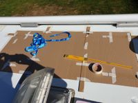
We build a template out of cardboard with which we determine the adhesive points of the individual rails on the roof for later panel installation and mark them with masking tape. The packaging material for the panels is ideal. But the cable entry through the roof must also be positioned and prepared.

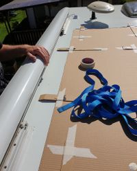


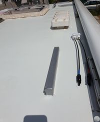
We now drill two holes for cable entry through the roof, apply paint to the holes and ensure that this leads to an elevation so that no condensation can later get inside the attached box. We have two solar controllers, so we also need two pass-through boxes. Since one of the factory plates was already there, we only added one can.
We position the aluminum rails to match the markings and glue them together after first applying a primer to the adhesive surface. We cleanly remove any excess adhesive residue with a spatula and remove the painter's tape. The adhesive then needs 24 hours to harden.


We mount the panels using the prepared terminals and connect the wiring. All cables are attached to the designated locations with cable ties, plug connections to the rails at a distance from the roof surface. It is important that no cable can chafe anywhere, even in strong winds.


We install the battery bank under the bed and the inverter directly in the tall cabinet in front of it. Everything as close as possible to the axle in order to have little influence on the weight distribution. The total installation together with the panels, the batteries and the inverter, together with all the cables and fastening materials, adds up to just under 200kg. This must be taken into account when determining the remaining payload. The batteries weigh around 120kg, the inverter weighs 14kg, and the panels drive around 30kg.
We also install Bluetooth transmitters so that you can conveniently control and monitor everything with your smartphone.


Experience from the last few years
We have had the first installation stage of the system in operation for almost seven years. With the last expansion, we have been on the move for four years. We use the vehicle all year round in all weather conditions. The battery bank is still working perfectly and has not shown any significant signs of wear so far.
We observe the following amounts of energy generated by the panels per day:
- Central Germany June/July: With sunshine around 450W around midday, up to 1.8kWh per day. In bad weather around 60W around midday, around 0.4kWh per day.
- Central Germany December/January: With sunshine around 80W around midday, up to 0.3kWh per day. No significant yield is expected in bad weather.
- Northern Spain June/July: With sunshine around 525W around midday, up to 2.5kWh per day. In bad weather around 100W around midday, around 0.7kWh per day.
- Spanish east coast December/January: With sunshine around 280W around midday, up to 1.4kWh per day. In bad weather around 40W around midday, around 0.3kWh per day.
- Mid Norway June: With sunshine around 435W around midday, up to 2,3kWh per day.
The pure material costs amount to more than €5,000. In direct comparison with the costs of shore power, installing a photovoltaic system in the camping sector is not a cost saving. Rather, it is an investment in the self-sufficiency gained, i.e. the independence of external electrical energy sources. But the system not only offers the advantage of the constant availability of electrical energy on the go. Many campsites have shore power connections limited to a maximum of 5A to 6A. If you want to operate a fully automatic coffee machine or other devices with a total output of over 1100W, you will have to limit yourself to these places if you cannot add electricity via your own installation. The Victron Multiplus Inverter is able to supplement energy to existing shore power smoothly and cleanly.
We are happy with our installation so far. It provides us with what we need and has not caused any technical problems so far.